Op.Amp Non-Inverting Amplifier
*OPAMP NON-INVERTING AMP
V1 3 0 0        sin( 0 1.2 500 )
R1 2 0  100
R2 1 2  100
X1 3 2 1        OPAMP
.SUBCKT OPAMP 1 2 6
R_in    1 2     10MEG
E_gain  3 0 1 2 100k
R_p1    3 4     1k
C_p1    4 0     1.59p
E_buffer        5 0 4 0 1
R_out   5 6     10
.ENDS
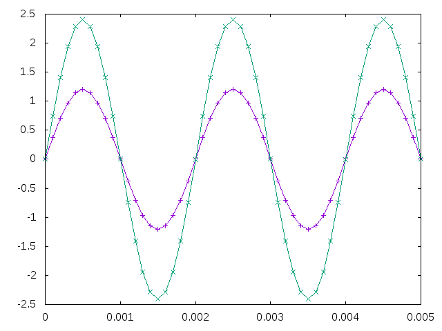
.PLOT TRAN v(3) v(1)
.TRAN .1m 5m 0
.END
.
Op Amp Non-Inverting Amplifier
- The voltage gain for the inverting configuration is set by the ratio of the feedback resistors R1 and R2.
Vo/Vi=-R2/R1
SIMULATION
- Plot the input V(3) and output V(1) of the Transient Analysis.
- The innards of the opamp device is defined by a subcircuit.
SEE ALSO

