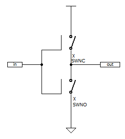
* SW Inverter
X1 3 2 1 0 SWNC
X2 2 0 1 0 SWNO
C1 2 0 0.05p
VCC1 3 0 5V
VIN 1 0 0V pulse ( 5 0 1ns 1ns 1ns 40ns 80ns)
.SUBCKT SWNO   1 2 3 4
S1 1 2 3 4 SW2
.ENDS
.SUBCKT SWNC   1 2 3 4
S2 1 2 4 3 SW1
.ENDS
.MODEL SW1 SW VT=-2.5V
.MODEL SW2 SW VT=2.5V
.OP
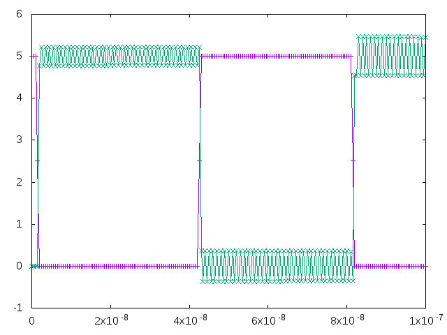
.TRAN 0.5ns 100ns
.PLOT TRAN v(1) v(2)
.END
.
Switches
- General form:
- SXXXXXXX N+ N- NC+ NC- MODEL
- Nodes N+ and N- are the nodes between which the switch terminals are connected.
- The model name is mandatory while the initial conditions are optional.
- For the voltage controlled switch, nodes NC+ and NC- are the positive and negative controlling nodes respectively.
SW SPice Model: SW1
- SPICE derective: .MODEL SW1 SW VT=-2.5V
- SPICE derective(On LTspice): .Model SW1 SW(Vt=-2.5)
- parameters
- VT:threshold voltage
SW SPice Model: SW2
- SPICE derective: .MODEL SW2 SW VT=2.5V
- SPICE derective(On LTspice): .Model SW2 SW(Vt=2.5)
- parameters
- VT:threshold voltage

